A screw thread is uniform shape which spirals around the inside or outside surface of a cylinder or cone. Like wedges, screws are simple machines. They are essentially a ramp or inclined plane wrapped into a helix, and the input to screws is torque rather than linear force. The mechanical advantage of a screw depends on its lead, which is the linear distance the screw travels in one revolution.
Screws used to fix objects in place are called fasteners, and screws used to move objects are called power screws or lead screws. In this chapter we will focus on power screws.
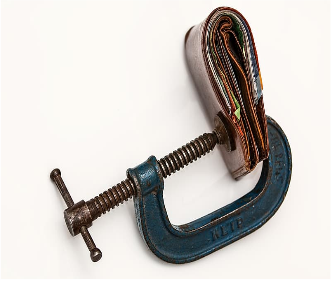
A power screw assembly includes a nut with matching internal threads which fits around the screw. There are two ways that a power screw can operate based on the movement of the screw and nut. In a scissors jack, the operator rotates the threaded rod with a crank fitted to the nut on the right, which is not threaded but acts as a thrust bearing. The nut on the left moves along the stationary screw to raise the load. In the C-clamp, the nut is stationary and the screw translates through as it rotates. In either case, a small moment on the screw can cause enormous forces on the nut, with the added benefit of the force being applied at a precise location as controlled by the screw.
Subsection9.4.1Screw Motion and the Right-hand rule
Most screw threads are right-hand threaded, which means they follow a right-hand rule as illustrated in Figure 9.4.2. When you use your right hand to then turn a right-handed thread towards your fingertips, it will move in the direction of your thumb. When you are look at the head of a bolt and rotate it clockwise, it tightens i.e.righty-tighty. The reverse, lefty-loosy, is also true.
situations where you do not want to mix up constituents. Cutting torches use right-hand thread for the oxygen and left-hand threads for the acetylene connections.
The motion of left-handed screws can either be thought of as opposite the right-hand rule or conforming to the same relationships if you use your left hand. Notice that right-handed threads slope up to the right, while left-handed threads slope down. Note that turning a thread upside-down does not reverse its handedness.
Although most thread profiles are V-shaped, we only consider square threads in this book. General purpose thread profiles, like NPT and ISO metric are more difficult to analyze.
The easiest way to analyze a square-thread power screw system is to turn the problem into a two-dimensional problem by ‘unwrapping’ the ramp from around the cylinder of the shaft. The significant geometrical properties of the thread are
The mean radius is the distance from the centerline to a point halfway between the tip and the root of the thread. Twice this value is the effective diameter.
The lead is the linear travel the nut makes in one revolution, which is also the distance from a point on the screw thread to a corresponding point on the same thread after one rotation. Threads are commonly designated by the number of threads per-inch or per-centimeter, and pitch is the inverse of this value.
The lead angle is related to the pitch and the mean radius by trigonometry. Using the right triangle shown in Figure 9.4.4(b), the thread lead angle \(\alpha\) is the inverse tangent of the ratio of the lead over the circumference
The focus of this section is to find the magnitude of a moment which will push a screw to impending motion. Impending motion is the threshold between the system holding still and moving, so knowledge of the moment required at impending motion allows you to interpret what happens to the screw system in static but not impending-motion conditions as well.
Assuming that motion is impending means that we can use the coefficient of static friction \(\mu_\text{s}\) and the related friction angle \(\phi_\text{s}\text{.}\) Recall from earlier in this chapter, that the friction angle \(\phi_\text{s}\) is related directly to \(\mu_\text{s}\) the by the equation:
SubsubsectionApplied Force Opposes Impending Motion
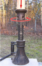
In this scenario we will examine the magnitude of moment \(M\) required to raise a screw to impending motion against the applied force \(W\) as shown in Figure 9.4.5(a). To eliminate any references to the orientation of the screw and force like up, down, left, or right, this type of motion will be described as “the applied force opposes impending motion.” This case occurs any time you are applying a force to an object with a screw.
The free-body diagram in Figure 9.4.5(b) shows the moment \(\vec{M}\) required to raise a load \(\vec{W}\) and the friction and normal forces acting on a slice of thread. These must be summed over the entire length of the thread to find the total friction and normal forces.
It is often easiest to express the friction force \(F\) and normal force \(N\) as the friction resultant \(R\) and the friction angle \(\phi_\text{s}\text{.}\) Recall that the friction force \(F\) direction always opposes the impending motion of the point of contact — in this case, the screw threads. Also, the thread angle \(\alpha\) determines the angle of the normal force \(N\) from the centerline of the screw. Finally, the friction angle \(\phi_\text{s}\) is the angle between the friction resultant force \(R\) and the normal force \(N\text{.}\)
Figure 9.4.7 is a free-body diagram of single thread element. \(W_i\) is the fraction of the total weight on this element, and the total moment \(M\) is represented by the fraction of the rotational force \(P_i\) acting at the mean radius \(r\) from the center of the screw
We next need to reduce these two equations to a single equation and also eliminate the difficulty to quantify \(\Sigma R\) term. Thus we solve both equations for \(\Sigma R\text{.}\)
\(M\) is the moment required to raise the screw to impending motion, \(W\) is the force load on the screw, \(r\) is the mean radius of the screw, \(\phi_\text{s}\) is the screw friction angle, and \(\alpha\) is the screw thread pitch.
Practically, this equation says that the moment to move a screw against an applied force must overcome the screw friction, represented by \(\phi_\text{s}\text{,}\) and the component of the load on the screw, represented by \(\alpha\text{.}\)
SubsubsectionApplied Force Supports Impending Motion
When the impending motion of the screw is in the direction of the applied force, we can also state that the “applied force supports impending motion.” This case occurs any time you remove a force held by a screw, like lowering the load supported by the screw jack in Figure 9.4.5(a).
This situation is a bit more complicated than the previous one, because there are three different possibilities depending on the relative magnitude of the friction angle \(\phi_\text{s}\) and the thread angle \(\alpha\text{.}\) Cases include
Self-locking. \(\phi_\text{s}\gt \alpha\).
In this case the load will not cause the screw to rotate by itself,
In all three cases the thread angle \(\alpha\) is the angle between the normal force \(N\) and the centerline of the screw, and the friction angle \(\phi_\text{s}\) is the angle between the friction resultant force \(R\) and the normal force \(N\text{.}\)
The derivations of the relationships are quite similar to the derivation of (9.4.1), but use subtly different free-body diagrams for each of the three cases. See Figure 9.4.8 below.
Self-locking screws are the type of screws that you will encounter most often in mechanical systems as they are highly predictable. They have sufficient friction available to hold their applied load even with no moment applied. Thus, they can safely carry a load in a static-but-not impending condition until you wish to overcome the excess friction by applying a moment \(M'\) to push them to impending motion.
Unwind-with-load screw As its name implies, an unwind-under-load screw will start turning unless a moment \(M''\) is applied to keep the screw at or beyond impending motion. The moment to push a self-locking screw to impending motion \(M'\) is in the opposite direction as the moment to keep unwind-under-load screws at impending motion \(M''\text{,}\) as \(M''\) is in the same direction as the moment to loosen (or raise) a screw. These unwind-with-load screws are not often found in mechanical systems, except for in dynamic motion control systems, where the screw is used to slow down motion.
To be designed in an unwind-with-load condition, a screw must have a quite steep thread angle \(\alpha\) and minimal friction between the threads and nut, which reduces \(\phi_\text{s}\text{.}\)
Impending-motion screw As the derived equations for all three unwind-with-load screw cases push the screw towards impending motion, when a screw is already at impending motion, it requires no applied moment to maintain equilibrium; however, this case is mechanically unstable. If the load increases slightly the screw will begin to unwind-under-load, whereas if the load decreases slightly the screw will become self-locking.
The concept of an applied force in the direction of impending motion works equally well for either a force applied in the impending motion direction of a screw, or for a force applied to the impending motion direction of a nut. An example of the first case is the screw jack lowering a load, and the second could be a scissors jack that has a rotating but non-translating screw, plus a non-rotating but translating nut.