
Section 6.1 Structures
Structures fall into three broad categories: trusses, frames, and machines, and you should be able to identify which is which.
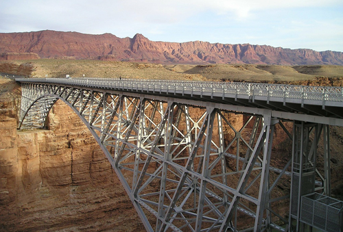
A truss is a multi-body structure made up of long slender members connected at their ends in triangular subunits. Truss members carry axial forces only. Trusses are commonly used for spanning large distances without interruption: bridges, roof systems, stadiums, aircraft hangers, auditoriums for example. They are also used for crane booms, radio towers and the like. Trusses are lightweight and relatively strong. Over the years many unique truss designs have been developed and are often named after the original designer.
A frame is a multi-part, rigid, stationary structure primarily designed to support some type of load. A frame contains at least one multi-force member, which a truss never has. This means that, unlike trusses, frame members must support bending moments as well as shear and normal forces. Many common items can be considered frames. Some examples: building structures, bike frames, ladders, scaffolding, and more.
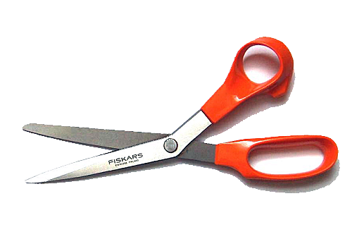
A machine is very similar to a frame, except that it includes some moving parts. The purpose of a machine is usually to provide a mechanical advantage and multiply forces. Pliers, scissors jacks, automobile suspensions, and construction equipment are all examples of machines.
Solving a structure means determining all forces acting on all of its parts. The solution typically begins by determining the global equilibrium of the entire structure, then breaking it into parts and analyzing each separate part. The specific process will depend on the type of structure, but will always follow the principles covered in the previous chapters.
Two-force Members.
Many structures contain at least one two-force member, and trusses consist of two-force members exclusively. Recall from Subsection 3.3.3 that a two-force body is an object subjected to exactly two forces. Two-force members are not required to be slender or straight but can be recognized because they connect to other bodies or supports at exactly two points, and have no other loading unless it is also applied at those points.
Identifying two-force members is helpful when solving structures because they automatically establish the line of action of the two forces. For a two-force body to be in equilibrium, the forces acting on it must be equal in magnitude, opposite in direction, and act along a line passing through the points where the two forces are applied. Since these points are known, the direction of the line of action is readily found.
The common way to express the force of a two-force member is with a magnitude and a sense, where the sense is either tension or compression. If the two forces tend to stretch the object we say it is in tension; if they act the other way and squash the object, it is in compression. The usual approach is to assume that a two-force member is in tension, then draw the free-body diagram and write the equilibrium equations accordingly. If the analysis shows that the forces are negative then they actually act with the opposite sense, i.e. compression.

