A wedge is a tapered object which converts a small input force into a large output force using the principle of an inclined plane. Wedges are used to separate, split or cut objects, lift weights, or fix objects in place. The mechanical advantage of a wedge is determined by the angle of its taper; narrow tapers have a larger mechanical advantage.
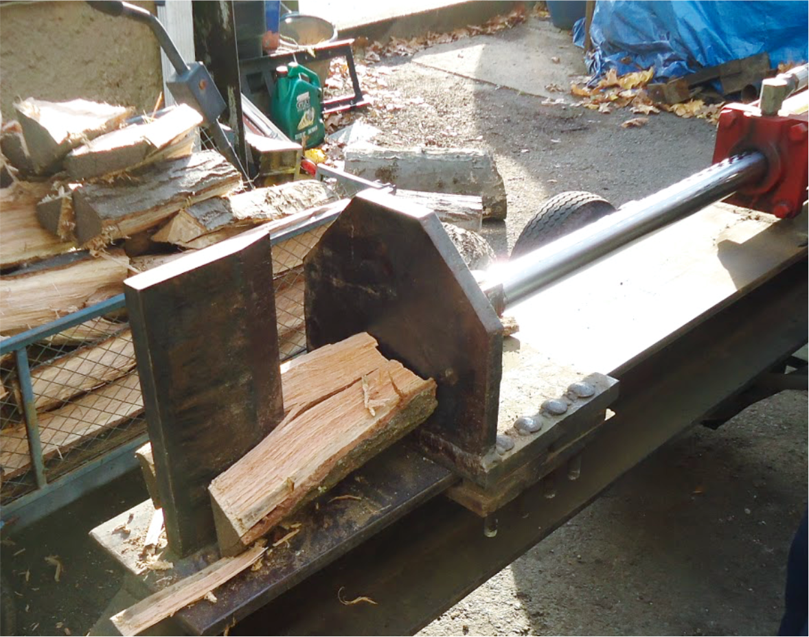
Low friction wedges are a simple machines which allows users to create large output forces to move objects using comparatively small input forces. In the log splitter in Figure 9.3.1(a), hydraulic ram pushes a log into a stationary wedge. The normal force pushes the two halves of the log apart while the friction force \(F_f\) is opposes the pushing force \(P\text{.}\)
High-friction (self-locking) wedges control the location of objects or hold them in place. Examples include doorstop wedges and carpentry wedges. The sailor in Figure 9.3.1(b) is hammering two wooden wedges towards each other to create large compressive forces to secure shoring timbers during a damage control operation.
Luckily the analysis of low- and high-friction wedges are identical and they are quite similar to the multi-force body equilibrium problems we saw in Chapter 5 and Chapter 6. The main difference is the inclusion of friction from all non-smooth contact surfaces. The directions of both the normal and friction forces on the free-body diagrams are defined below.
Normal forces act between bodies act perpendicular to the contacting surfaces. All normal forces on a free-body diagram should be pointing towards the body because wedges are always subjected to compression.
Friction forces are between bodies which act parallel or tangential to the contacting surfaces and are created by the microscopic or large scale roughness of the surfaces. All friction forces on a free-body diagram should be drawn pointing in the direction which resists relative motion at the point of contact.
The key added challenge of solving wedge problems is that the angled faces of wedges usually need to be resolved into components in the \(x\) and \(y\text{,}\) unless a different coordinate system is used.
One of the critical steps in solving block or wedge problems is to determine which force is engaging the friction of the system. Start by drawing the friction forces on the body where this force acts. As you pass the friction and normal forces to adjacent free-body diagrams, you must always show them as equal and opposite, action-reaction pairs. This is illustrated in the following example.
There are still two unused equilibrium equations for this free-body diagram, but they are not sufficient to find unknown forces \(P\) and \(R\) because the point where resultant friction force acts is also unknown.
Next, consider equilibrium of the block, Figure 9.3.3(b). A detail of \(N_2\) and \(F_2\) in Figure 9.3.4 shows how the their \(x\) and \(y\) components are related to the wedge angle \(\theta\text{.}\)
With the friction and normal forces on both sides of the wedge known, we can now find the required force \(P\) using the free body diagram of the wedge 9.3.3(c).
This problem still requires a free-body diagram for each block and wedge. The only difference between it and the previous example is that the impending motion for the wedge is now to the left. Thus, the friction forces on the top and bottom of the wedge are to the right and are both still at impending motion.