Disc friction refers friction between a flat, rotating body and a stationary surface. Disc friction exerts a moment on the bodies involved which resists the relative rotation of the bodies. Disc friction is applicable to a wide variety of designs including end bearings, collar bearings, disc brakes, and clutches.
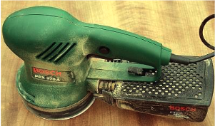
Figure9.7.1.This orbital sander rotates a circular sanding disc against a stationary surface. The disc friction between the sanding disc and the surface exert a moment on both the surface and the sander.
A collar bearing, shown inFigure 9.7.2 has a rotating annular area in contact with a stationary bearing surface. The rotating shaft passes through a hole or bearing in the surface to maintain radial alignment. The collar bearing prevents axial motion and acts as a thrust bearing to transfer the axial load to a solid foundation.
The friction force at any point of the contact area will equal the normal force at that point times the kinetic coefficient of friction at that point. If the coefficient of friction and the pressure between the collar and the surface is the same at all points, then the same friction force at every point is the same as well. This does not mean that the moment exerted at every point is equal as well. Elements towards the outside of the contact area cause larger moments than those closer to the center since they have larger moment arms.
The total moment exerted acting on the disc due to the friction forces is found by integrating the elements \(dM\) over the contact area. The moment of each element will be equal to the product of the coefficient of kinetic friction, the normal force pressure, the moment arm and the area of each element
\begin{equation*}
dM=\mu_k p r\; dA\text{.}
\end{equation*}
\begin{align*}
M\amp =\int_A dM\\
\amp=\int_A \mu_k p r \; dA
\end{align*}
The coefficient of friction and pressure terms are constant so can be moved outside the integral, and since pressure is defined as force per unit are area \(p = F/A\text{,}\) the pressure term can be replaced with the applied load divided by the bearing contact area,
\begin{equation*}
p = \frac{P}{\pi (r_o^2 -r_i^2)}\text{.}
\end{equation*}
In cases where we have a solid circular contact area such as with a solid circular shaft, an end bearing, or the orbital sander shown in Figure 9.7.1 we simply set the inner radius to zero and simplify equation (9.7.1). If we do so, the result is
\begin{equation}
M=\frac{2}{3} \mu_k F r_\text{o}\text{.}\tag{9.7.2}
\end{equation}
Disc brakes, due to their smaller contact area, have higher pressure for the same applied force but a smaller area over which to exert friction. In the end, these factors cancel out and we end up with the same formula we found in Subsection 9.7.2. Notice that this formula is independent of \(\theta\text{.}\)