Logo image

Engineering Statics: Open and Interactive

Section 10.4 Composite Shapes

In this section we will find the moment of inertia of shapes formed by combining simple shapes like rectangles, triangles and circles much the same way we did to find centroids in Section 7.5.
The procedure is to divide the complex shape into its sub shapes and then use the centroidal moment of inertia formulas from Subsection 10.3.2, along with the parallel axis theorem (10.3.1) to calculate the moments of inertia of parts, and finally combine them to find the moment of inertia of the original shape.

Subsection 10.4.1 Composite Area Method

For a composite shape made up of \(n\) subparts, the moment of inertia of the whole shape is the sum of the moments of inertia of the individual parts, however the moment of inertia of any holes are subtracted from the total of the positive areas.
Moments of inertia are always calculated relative to a specific axis, so the moments of inertia of all the sub shapes must be calculated with respect to this same axis, which will usually involve applying the parallel axis theorem.
\begin{align} I \amp = \sum_{i=0}^{n} (I)_i \ = \sum_{i=0}^{n} \left (\bar{I}+A d^2 \right )_i \tag{10.4.1} \end{align}
.
The method is demonstrated in the following examples.

Example 10.4.1. Beam Design.

You have three \(\ft{24}\) long wooden 2\(\times\)6’s and you want to nail them together them to make the stiffest possible beam. The stiffness of a beam is proportional to the moment of inertia of the beam’s cross-section about a horizontal axis passing through its centroid. The actual dimensions of nominal 2\(\times\)6 lumber are \(\inch{1.5}\) by \(\inch{5.5}\text{.}\)
Three wooden segments arranged vertically so the height is 6" and width is three beams times 2" per beam.
Three wooden segments arranged in the shape of the capital letter I.
Which of the arrangements will be the stiffest, and what is the ratio of the two moments of inertia?
Answer.
\begin{align*} (I_x)_1 \amp = \inch{62.4}^4\\ (I_x)_2 \amp = \inch{226}^4 \end{align*}
The I-beam has more than 3.6 times the stiffness of the sandwich beam!
Solution.
Given: \(b = \inch{1.5}\text{,}\) \(h=\inch{5.5}\text{.}\)
In case 1 the centroids of all three rectangles are on the \(x\) axis, so the parallel axis theorem is unnecessary.
\begin{align*} (I_x)_1 \amp = \sum_{i= 1}^3 \bar{I} + A d^2\\ \amp = 3 \frac{bh^3}{12} \\ \amp = \frac{(1.5)(5.5)^3}{4} \\ (I_x)_1 \amp = \inch{62.4}^4 \end{align*}
This value is the same as the moment of inertia of a \((\inch{4.5} \times \inch{5.5})\) rectangle about its centroid.
In case 2, the parallel axis theorem must be used for the upper and lower rectangles, since their centroids are not on the \(x\) axis.
\begin{align*} (I_x)_2 \amp = \sum_{i = 1}^3 \bar{I} + A d^2\\ \amp = \left( \frac{bh^3}{12} \right) + 2 \left[ \frac{1}{12}hb^3 + (bh) ( h/2 + b/2 )^2 \right]\\ \amp = \frac{(1.5)(5.5)^3 }{12} + 2\left[ \frac{(1.5)^3(5.5)}{12} + (1.5 \times 5.5)(3.5)^2 \right ]\\ \amp = \inch{20.8}^4 + 2 \left[ \inch{1.547}^4 + \inch{101.6}^4 \right ] \\ (I_x)_2 \amp = \inch{226}^4 \end{align*}
\begin{equation*} (I_x)_2 / (I_x)_1 = 3.61 \end{equation*}
The I-beam is about 3.6 times stiffer than the sandwich beam. This optimization of material usage is the reason we use I-beams.

Example 10.4.2. T Shape.

T-shape. Horizontal segment is 90 mm wide by 20 mm tall. Below that, the vertical segment is 30 mm wide by 60 mm tall.
Find the moment of inertia of the T shape about the \(x\) and \(y\) axes.
Answer.
\begin{align*} I_x \amp = (I_x)_1 + (I_x)_2 \amp = \mm{11.04 \times 10^6}^4\\ I_y \amp = (I_y)_1 + (I_y)_2 \amp = \mm{8.64 \times 10^6}^4 \end{align*}
Solution.
  1. Strategy.
    Divide the T shape into a \(\mm{30} \times \mm{60}\) vertical rectangle (1), and a \(\mm{90} \times \mm{20}\) horizontal rectangle (2) then add the moments of inertia of the two parts.
    \begin{align*} I_x \amp = (I_x)_1 + (I_x)_2 \amp I_y \amp = (I_y)_1 + (I_y)_2 \end{align*}
  2. MOI about the \(x\) Axis.
    The bottom edge of rectangle 1 is on the \(x\) axis. Using the formula from Subsection 10.3.2 gives
    \begin{equation*} (I_x)_1 = \frac{bh^3}{3} =\frac{ (30)(60)^3}{3} = \mm{2.16 \times 10^6}^4\text{.} \end{equation*}
    The centroid of rectangle 2 is located \(\mm{70}\) above the \(x\) axis so we must use the parallel axis theorem (10.3.1), so
    \begin{align*} (I_x)_2 \amp = \bar{I} + A d^2\\ \amp = \frac{b h^3}{12} + (b h) d^2 \\ \amp = \frac{(90)(20)^3}{12} + (90 \times 20) ( 70)^2 \\ (I_x)_2 \amp = \mm{8.88 \times 10^6}^4 \end{align*}
    .
    The moment of inertia of the entire T shape about the \(x\) axis is the sum of these two values,
    \begin{equation*} I_x = (I_x)_1 + (I_x)_2 = \mm{11.04 \times 10^6}^4\text{.} \end{equation*}
  3. MOI about the \(y\) Axis.
    We can use the same procedure to find the moment of inertia about the \(y\) axis, however it is usually more convenient to organize all the necessary information in a table rather than writing the equations explicitly.
    We will use the parallel axis theorem for both rectangles with \(d\) representing the distance between the \(y\) axis and the centroid of the part. In this example \(d\) is the same for both parts, but that will not always be true.
    Part Dimensions \(\bar{I}_y = hb^3/12\) \(A=bh\) \(d\) \(A d^2\) \(I_y=\bar{I} + A d^2\)
    Units \(\text{mm}\) \(\text{mm}^4\) \(\text{mm}^2\) \(\text{mm}\) \(\text{mm}^4\) \(\text{mm}^4\)
    1 \(b= 30,\ h=60\) \(135\times 10^3\) \(1800\) \(45\) \(3.645 \times 10^6\) \(3.78 \times 10^6\)
    2 \(b =90,\ h=20\) \(1.215 \times 10^6\) \(1800\) \(45\) \(3.645 \times 10^6\) \(4.86 \times 10^6\)
    Total \(8.64 \times 10^6\)
    \begin{equation*} I_y = (I_y)_1 + (I_y)_2 = \mm{8.64 \times 10^6}^4 \end{equation*}

Example 10.4.3. Fillet.

L-shaped segment 10 in high by 9 in at the base, thickness is 3". The fillet at the interior of the L-shape has a radius of 3".
Find the moment inertia of the area about the \(x\) axis.
Answer.
\begin{equation*} I_x = \inch{1080.6}^4 \end{equation*}
Solution.
  1. Strategy.
    First, divide the area into four parts:
    1. a \(\inch{9} \times \inch{3}\) rectangle
    2. a \(\inch{6} \times \inch{3}\) rectangle
    3. a \(\inch{3} \times \inch{4}\) rectangle, and
    4. a removed quarter-circle with a \(\inch{3}\) radius.
    Then set up a table and apply the parallel axis theorem (10.3.1) as in the previous example. Since the quarter-circle is removed, subtract its moment of inertia from total of the other shapes.
  2. MOI about the \(y\) Axis.
    The centroidal moment of inertia of a quarter-circle, from Subsection 10.3.2 is
    \begin{align*} I_x\amp = \left(\frac{\pi}{16} - \frac{4}{9\pi}\right) r^4\\ \amp = 0.0549\ r^4 \end{align*}
    The distance from the top edge of the quarter-circle down to its centroid is \(\dfrac{4r}{3\pi}= \inch{1.273}\text{,}\) so the distance from the \(x\) axis to its centroid is
    \begin{equation*} d = 6 - 1.27 = \inch{4.727}\text{.} \end{equation*}
    Fill out the table of information.
    Part Dimensions \(\bar{I}_x\) \(A\) \(d =\bar{y}\) \(A d^2\) \(I_y=\bar{I} + A d^2\)
    Units \(\text{inch}\) \(\text{inch}^4\) \(\text{inch}^2\) \(\text{inch}\) \(\text{inch}^4\) \(\text{inch}^4\)
    1 \(b= 9,\ h=3\) \(bh^3/12 = 20.25\) \(27\) \(1.5\) \(60.75\) \(81\)
    2 \(b =6,\ h=3\) \(bh^3/12 = 13.5\) \(18\) \(4.5\) \(364.5\) \(378\)
    3 \(b= 3,\ h=4\) \(bh^3/12 = 16\) \(12\) \(8\) \(768\) \(784\)
    4 \(r=3\) \(0.0549\ r^4 = 4.45\) \(7.07\) \(4.727\) \(158.0\) \(162.4\)
    Take care to subtract the moment of inertia of the removed quarter-circle from the total.
    \begin{equation*} I_x = (I_x)_1 + (I_x)_2 + (I_x)_3 - 1 (I_x)_4 = \inch{1080.6}^4\text{.} \end{equation*}

Example 10.4.4. Concrete Pipe Casing.

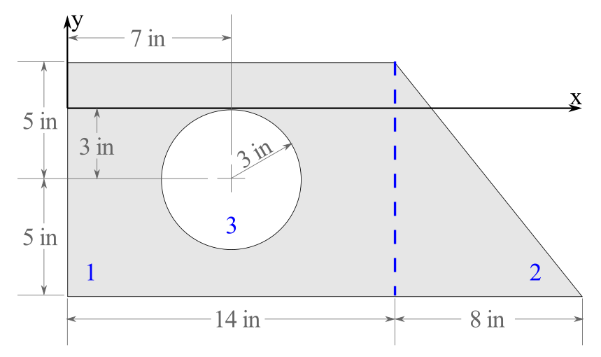
The cross section of a concrete pipe casing composed of a rectangular block, a triangular wedge, and a circular pipe formed through the middle of the block is shown below.
As the pipe casing will be subject to various loads, find the area moment of inertia of the cross section about the \(x\) and \(y\) axes.
Composite shape made of a rectangle with a circle cut off. A right triangle is flush with the right side of the rectangle. The coordinates are displayed in the following table.
Answer.
\begin{align*} I_x \amp = \inch{3202}^4 \amp I_y \amp = \inch{18951}^4 \end{align*}
Solution.
  1. Strategy.
    Organize all the necessary information into a table, then total the moments of inertia of the parts to get the moment of inertia of the whole shape. Remember that the hole is removed from the shape, so its contribution to the total moment of inertia is negative.
  2. Table.
    Part \(A_i\) \(d_{x_i}\) \(d_{y_i}\) \(A_i d_{x}^2\) \(A d_{y}^2\) \(\bar{I}_x\) \(\bar{I}_y\)
    Units \(\text{in}^2\) \(\text{in}\) \(\text{in}\) \(\text{in}^4\) \(\text{in}^4\) \(\text{in}^4\) \(\text{in}^4\)
    Rectangle 1
    \(b = 14,\)
    \(h = 10\)
    \(bh\)
    \(=140\)
    7 -3 6860 1260 \(bh^3/12\)
    \(=1167\)
    \(b^3h/12\)
    \(=2287\)
    Triangle 2
    \(b = 8,\)
    \(h = 10\)
    \(bh/2\)
    \(=40\)
    16.67 -4.67 11111 871.1 \(bh^3/36\)
    \(=222.2\)
    \(b^3h/12\)
    \(=142.2\)
    Circular Hole 3
    \(r = 3\)
    \(-\pi r^2\)
    \(=-28.27\)
    7 -3 -1385 -254.5 \(-\pi r^4/4\)
    \(=-63.62\)
    \(-\pi r^4/4\)
    \(=-63.62\)
    Total 151.7 16586 1877 1325 2365
  3. Total.
    \begin{align*} (I_x)_1 \amp = \left[ \bar{I}_x + A d_y^2 \right]_1= \inch{2427}^4 \amp (I_y)_1 \amp = \left[\bar{I}_y + A d_x^2\right]_1 = \inch{9147}^4\\ (I_x)_2 \amp = \left[\bar{I}_x + A d_y^2\right]_2 = \inch{1093}^4 \amp (I_y)_2 \amp = \left[\bar{I}_y + A d_x^2\right]_2 = \inch{11253}^4\\ (I_x)_3 \amp = \left[\bar{I}_x + A d_y^2\right]_3 = -\inch{318.1}^4 \amp(I_y)_3 \amp = \left[\bar{I}_y + A d_x^2\right]_3 = -\inch{1449}^4\\ I_x \amp = \sum (I_x)_i =\inch{3202}^4\amp I_y \amp = \sum (I_y)_i = \inch{18951}^4 \end{align*}
    Alternately, you could find the moments of inertia by adding the sums of the columns, since you are adding the same values together, just in a different order.
    \begin{align*} I_x \amp = \sum \bar{I}_x + \sum Ad_y^2=\inch{3202}^4\amp I_y \amp = \sum \bar{I}_y + \sum A d_x^2= \inch{18951}^4 \end{align*}

Example 10.4.5. Interactive: Composite Rectangles.

This interactive shows a composite shape consisting of a large rectangle with a smaller rectangle subtracted. You can change the location and size of the rectangles by moving the red and blue points.
Use the interactive to see how changes to the rectangles affects the moments of inertia of this shape about the system \(x\) axis. Notice that for two-part shapes like this, the centroid of the composite shape is on the line connecting the centroids of the two parts.
For calculations, it is convenient to collect all the needed information in a table as is done here.
Instructions.
Demonstrates calculation of the moment of inertia of a composite shape about the \(x\) axis using the parallel axis theorem
\begin{equation*} I = \bar{I} + A d^2 \text{.} \end{equation*}
Note that when using the parallel axis theorem, area is always positive, and the MOI of the hole \(I_2\) is subtracted from \(I_1\) to get the MOI of the combined shape.
Figure 10.4.6. Moment of Inertia of a Rectangle about the \(x\) axis.

Subsection 10.4.2 Structural Steel Sections

Steel is a strong, versatile, and durable material commonly used for girders, beams, and columns in steel structures such as buildings, bridges, and ships. When possible designers prefer to use prefabricated Standardized Structural Steel to minimize material cost.
Structural steel is available in a variety of shapes called sections, shown below. These include universal beams and columns (W, S), structural channels (C), equal and unequal angle sections (L), Tee shapes (T), rectangular, square and round hollow structural sections (HSS), bar, rod, and plate. All are available in a range of sizes from small to huge. Steel sections are manufactured by hot or cold rolling or fabricated by welding flat or curved steel plates together.
Left to right Wide-Flange-wide I-shape, American Standard thin I-shape, Channel-thin square C-shape, Equal Angle wide L-shape, Unequal Angle- L-shape, Structural Tee T-shape, Rectangle shape, Square, Round.
Figure 10.4.7. AISC Standard Sections: Left to right -- Wide-Flange (W), American Standard (S), Channel (C), Equal Angle (L), Unequal Angle (L), Structural Tee (T), Rectangle (HSS), Square (HSS), Round (HSS).
Designers and engineers must select the most appropriate and economical section which can support the potential tension, compression, shear, torsion and bending loads. Tables of properties of Standard Steel Sections are published by the American Institute of Steel Construction, and are used to simplify the process. The tables contain important properties of the sections, including dimensions, cross sectional area, weight per foot, and moment of inertia about vertical and horizontal axes. An abbreviated subset of the AISC tables are available in Appendix D.
In this section we will use the information in the AISC tables to find the moments of inertia of standard sections and also of composite shapes incorporating standard sections.
The top and bottom pieces of an I-beam are called flanges. The middle portion is referred to as the web. The flanges take most of the internal compression and tension forces as they are located the furthest from the neutral axis, and the web mainly acts to support any shear forces and hold the two flanges apart. The transverse axis through the centroid of the cross section is called the neutral axis, and cutting plane through the beam at the neutral axis is called the neutral plane, or neutral surface. This surface does not lengthen or shorten during bending.
Top and bottom of beam are flanges. Vertical center column is the web. Depth is top to bottom measurement. Neutral axis and neutral plane intersect the centroid.
Figure 10.4.8. Beam Nomenclature

Example 10.4.9. Built-up beam.

A built-up beam consists of two L6\(\times \)4\(\times\)1/2 angles attached to a 8\(\times\)1 plate as shown. Determine
  1. the distance from the \(x\) axis to the neutral axis, which passes through the centroid of the combined shape, and
  2. the moment of inertia of the combined shape about the neutral axis.
A built-up beam of L6 x 4 x 1/2 angles attached to a 8 x 1 plate.
Answer.
\begin{align*} \bar{y} \amp \amp = \inch{0.846}\\ I_{x'} \amp \amp = \inch{61.98}^4 \end{align*}
Solution.
  1. Strategy.
    Determine the properties of the sub shapes with respect to the \(x\) axis, and then use them to find the neutral axis.
    Use the parallel axis theorem to find the moment of inertia of the parts with respect to the neutral axis.
    Take advantage of the fact that the two angles are identical and positioned similarly.
  2. Find the neutral axis.
    For one L\(6\times 4\times 1/2\) angle, from Section D.1
    \begin{align*} A_\text{L} \amp = \inch{4.75}^2\\ \bar{y}_\text{L} \amp = \inch{1.98}\\ \bar{I}_\text{L} \amp = \inch{17.3}^4 \end{align*}
    .
    For the \(b = \inch{8},\)\(h = \inch{1}\) rectangle
    \begin{align*} A_\text{R} \amp = bh = \inch{8}^2\\ \bar{y}_\text{R} \amp =-h/2 = \inch{-0.5}\\ \bar{I}_\text{R} \amp = \frac{bh^3}{12} = \frac{8}{12} = \inch{0.667}^4 \end{align*}
    .
    Find the distance to the neutral axis
    \begin{align*} \bar{y} \amp = \frac{\sum A_i \bar{y_i}}{\sum A_i} = \frac{ 2 A_\text{L} \bar{y}_\text{L} + A_\text{R} \bar{y}_\text{R} } {2 A_\text{L} + A_\text{R}}\\ \amp = \frac{ 2 (4.75)(1.98) + (8)(-0.5)} { 2(4.75) + 8}\\ \bar{y} \amp = \inch{0.846} \end{align*}
    .
  3. Find the Moment of Inertia.
    The distance between the neutral axis is and the centroids of the subparts are
    \begin{align*} d_\text{R} \amp = | \bar{y} - \bar{y}_\text{R} | = | 0.846 - (-0.5)| = \inch{1.346}\\ d_\text{L} \amp = | \bar{y} - \bar{y}_\text{L} | = | 0.846 - 1.98| = \inch{1.134} \end{align*}
    .
    The moment of inertia of the rectangle about the \(x'\) axis
    \begin{align*} (I_x')_\text{R} \amp = [\bar{I} + A d^2]_\text{R}\\ \amp = 0.667 + (8)(1.346)^2 \\ \amp = \inch{15.16}^4 \end{align*}
    .
    The moment of inertia of one angle about the \(x'\) axis
    \begin{align*} (I_x')_\text{L} \amp = [\bar{I} + A d^2]_\text{L}\\ \amp = 17.3 + (4.75)(1.134)^2 \\ \amp = \inch{23.4}^4 \end{align*}
    .
    The moment of inertia of the built up beam about the neutral axis
    \begin{align*} I_{x'} \amp = \sum (I_{x'})_i \\ \amp = 2 (I_{x'})_\text{L} + (I_{x'})_\text{R} \\ \amp = 2(\inch{23.4}^4) + \inch{15.16}^4\\ I_{x'} \amp = \inch{61.98}^4 \end{align*}
    .